ad 1

Friday, May 24, 2013

P-51C Mustang Engine - Painting

So now painting begins on the engine and I had to take a few lessons from the late Bob Ross on this one. Now I have painted several models, I know airbrushing pretty well, but it still amazes me how much you can learn even if you have mastered something. For instance: I had all my engine components glued on toothpicks and had bought a bottle of Model Master Semi-gloss black and was ready to start airbrushing. I went to mix the paint with my airbrush thinner and it wouldn't mix. It was like oil and water. I looked at the paint bottle and realized I had bought acrylic paint, not enamel. At first I was quite annoyed that I had no way to airbrush acrylic paints, but then I grabbed a brush and painted a little piece of scrap plastic just to see how it came out. I was pleasently surprised that this acrylic paint left no brush marks on the plastic. Lightbulb! So I test painted one of my components and sure enough, it looks like it was airbrushed. No brush marks. So as Bob Ross would say, we don't have mistakes, we have happy accidents. There is however a method to be followed when painting anything.

In order to prevent brush marks, the paint in the brush has to be kept wet. If you have ever painted a large area before, you may have noticed that when you first start brushing the paint goes on nice and smooth. But as you continue streaks start to appear and the bristles become stiff. This is because the paint in the bristles is starting to dry and it sticks the bristles together. This is what forms the brush marks. You need to continually clean the brush while you paint. I keep a jar of lacquer thinner on my paint carousel and every couple of minutes I clean off the brush, dry it, and reshake my paint. Taking the extra minute to do this can really make a difference in the paint job.

Since fully black painted parts don't really look that good in pictures, I didn't take any of the painting process. I think you know what painted parts look like. So onto the detailing. On most Merlin engines that I have seen the engine is painted black, but the nuts and bolts are a natural metal color. So on my model the nuts and bolts have to be painted aluminum. Luckily the model is detailed enough to have a few hundred fasteners molded onto it, but painting tiny little things like this without messing up the paint around it is the real challenge. Again, I took a lesson from Bob Ross. Time to pull out the knife. I found that the best way to paint these fasteners was by dipping the tip of my X-acto knife in the paint and lightly touching it to the part. Now the idea behind this is not have big aluminum blobs, its to create subtle glistens. Its a detail that really won't be obvious, except to the trained detail-oriented eye. Others will see it after I point it out, I'm sure. But if you look at the pictures below, you'll see that these tiny little details can really make the engine look good and are well worth the time.


Friday, May 17, 2013

P-51C Mustang Engine Details - Continued

There were a few more details to scratchbuild before painting could begin. I used the same methods mentioned in the last blog to assemble the oil filter and the duel drive. It's odd that a kit as detailed as this would leave off the duel drive that is mounted to the front of every Merlin directly below the propellor shaft. Even the Trumpeter kit has this detail, it looks like crap, but at least it has it.

The oil filter was fairly simple. The worst parts were trying to figure out how to simulate the bolts. I eventually used very thin wire cut to length. I cut slots in the flange with a thin razor saw and epoxied the wire in place.


The duel drive presented a fun challenge since it has to fit inside the engine mount framing and that hasn't been built yet. I guess that will make it a challenge later in the project. Using several images, I broke the component down into basic shapes using a .080" rod as a base to hold everything together.


I slid all the pieces together on the rod like a shish-ka-bob and added the details.


There were a few hose connections made from .030" rod and cut them down after the glue dried.


Here you can see the size of all the details. Next up...painting

Thursday, May 9, 2013

P-51C Mustang Engine - Oil Relief Valve

So I've realized that when scratchbuilding you have to be willing to fail a few times in order to end up with something that looks good. In the last blog I talked about the oil relief valve and how it would look much better if it was scratchbuilt. This is true, however the process took me a while and I had to check several sources of reference to get a good picture of it. The problem when you do these sorts of projects, especially with older aircraft, is that you will find ten different versions of the same part or component and since most of these aircraft have been restored using more modern parts it is hard sometimes to separate history from modern efficiency. Luckily I have the 1944 release of the Rolls-Royce Merlin V-1650 overhaul manual. I actually found a good picture of the oil relief valve in the back of the manual in a diagram showing how the spare parts bin should be set up. It's odd sometimes where you find information, so don't be afraid to look in weird places for references.

Ok let's get into it. So first I tried to use an image I found online, but I couldn't really see how the relief valve looked. The simpliest way to create a scratchbuilt part like this is to break it down into simple shapes, and with this image, I couldn't see the real shapes. So I went with what I saw. The next couple pictures do not show the final relief valve, but they will give you a good idea of how the beginning of the scratchbuilding process. Start with a base of basic shapes. Details come later. I started with simple plastic rod and strip and started arranging them as I thought I saw in the image.


Now as good as this may look at a start, granted there are no details, this actually isn't how the valve looked. But at least you can get a good idea of how some simple shapes can be formed to make something that looks complex. And had I used this in the model, no one except a Merlin mechanic would be able to tell me that I was wrong. However, anything can be done better and when I found a really good image of the relief valve and could break down the component into simple shapes, I realized I could do it much, much better.

I started with a piece of .030" x .060" and cut and filed it to the proper shape. I left a "tail" on the strip so that it would be easier to handle while assembling. The component will eventully be cut off.


I glued a .040" rod to the bottom and started adding the simple shapes, some half rounds and strips. The rods sticking out the sides will be where the oil lines will eventually connect. I made them intentionally long so its easier to hold while gluing it. This is a trick when scratchbuildling that most people don't see with they look at the finished product. They see all these little parts and wonder what tiny tweezers and magnifiers were used to glue the parts in place. I just used my fingers. Remember, you can always cut and sand them down to the proper length later. A tip: Make sure the glue has dried completely before cutting it or you will definitely ruin your day.


The relief valve was held to the side of the engine with 8 bolts which will be represented by some very thin wire. But first I need the mounts. These were made with .020" rod glued into position. Its hard to see in this image, but they were left long and cut down.


All the rods were cut and filed down to the right length and .010" holes were drilled as close to center as possible. A few details were added to the top with .040" rod and .020" wire.


.008" wire was fed through the holes and epoxied in place. Again, the wires were longer than needed when I installed them. I made sure that the exposed wire on the front of the part were the proper length and allowed the excess to stick out the back. It would be much easier to cut the end that wouldn't be seen. So why make these out of actual wire. Well, this will eventually be painted black like the rest of the engine, but the bolts will be an aluminum color. So once its painted, I'll simply take an X-Acto knife and scrape the paint away from the bolts. This is much easier than trying to paint them afterwards. And I don't have any plastic that thin.

 
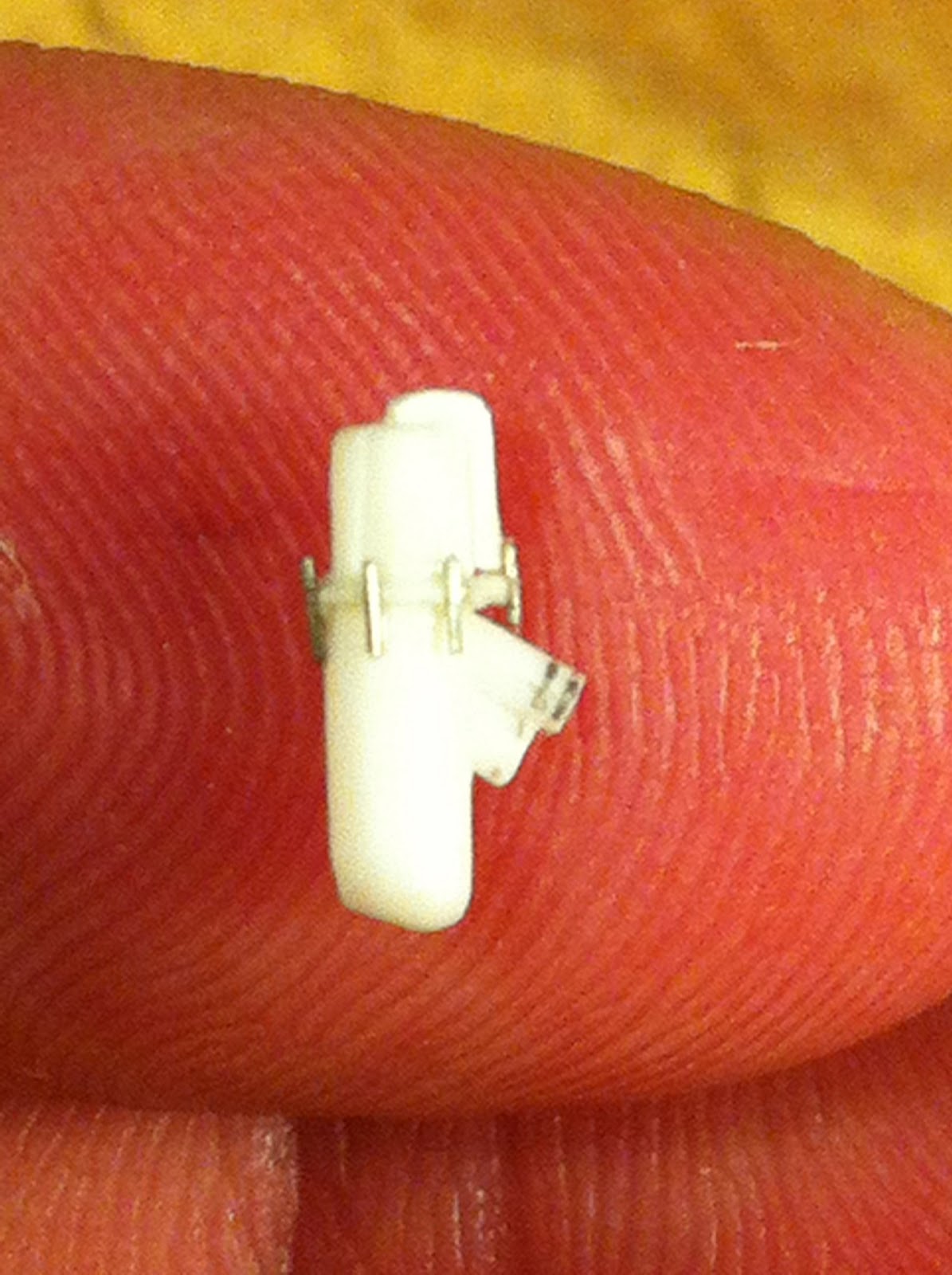
So after cutting off the "tail" and adding a few more details, here is the finished oil relief valve.