ad 1

Showing posts with label Engine. Show all posts

Thursday, October 3, 2013

P-51C Mustang Rolls Royce Merlin Engine Completed

Finally after several months of work, the engine to my 1/32 Tamiya P-51C Mustang is completed. I had some pictures taken on a good camera to get a decent all around view of the engine. Next I'll be doing the firewall and oil tank as soon as I get the time. Until then, enjoy the engine pictures.


Tuesday, September 10, 2013

P-51C Mustang Engine - Fuel lines and Atomizers

I almost missed some really cool details on top of the engine. I found them while trying to figure out where, what I thought was, the last fuel line actually ran. On the top of the engine are 6 fuel atomizers connected with a very thin fuel line that leads back to a splitter connecter, can't think of the actual name for it, but since I'm still in the process of building that it will be mentioned in the next blog.

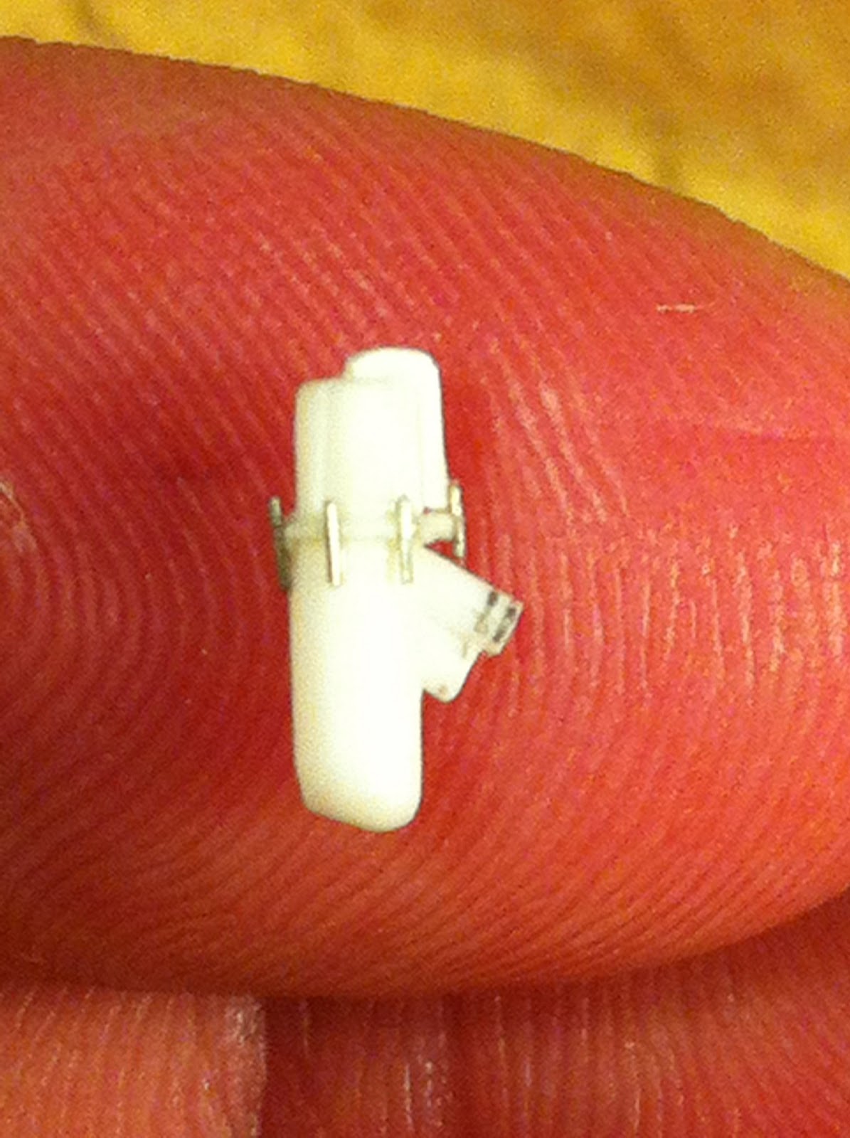
Each Atomizer was made with a piece of .040: plastic rod and a thin wire that was folded into a "U" shape. I used the side edge of a razor blade to fold the wire. It was then very carefully glued in place on the wire. At this point the wire legs were longer than what you see in the picture below. This made it so much easier to handle while gluing it in place. Once the glue was dry I used fingernail clippers to snip them to the proper length.


As you can see in the picture above, there are three colors on this tiny little thing. The outside of the rod is black, the top face of the rod is gold, and the prongs of the wire are silver. Once the paint tried, I carefully cut the end of the rod off leaving the thinnest sliver behind. Forgive the blurriness of the photo. My camera can't focus on things this small, but for size reference, the atomizer is sitting on a piece of college rule notebook paper.


The atomizers were glued in place on top of the engine.


The fuel lines that connect the atomizers have a neat joggle in them which proved to be quite the pain until I made a jig to bend them on. I used the placement of each atomizer to make this jig out of a popsicle stick. I bend the wire over it and test fit it on the engine, tweaking the jig as necessary.


I used a very thin .007" wire for the fuel line. It bends very easy, but is very finicky. You have to be careful when handling wire this thin cause you can spend 10 minutes bending the perfect joggle then accidentally knock it totally out of shape. The fuel line runs underneath the ignition wires already in place. The two lines are mirror images of each other. The picture below shows the two lines in place on the atomizers.


Only a few more things and the engine will be complete...

Wednesday, August 28, 2013

P-51C Mustang Engine and Supercharger Details

The left side of the engine has a few less details than the right side, but this doesn't mean that you can't add a few little things to spice it up. One of the lines on this side is connected to the intercooler with a rubber hose held in place with metal clamps. I first cut and bent a paperclip to simulate the line. Then I carefully masked it off and painted the end with a few layers of gray paint to simulate the rubber hose.


I cut a thin strip of soda can aluminum and bent it around another piece of paperclip to create the curved shape. Once the pieces were glued in place, they look very much like metal clamps holding the rubber tube in place. I'll admit, they could have looked a little tighter, but sometimes you just have to live with what you got.


Another paperclip was used to make the second main line on this side. I couldn't see where the top of this line connected on the real engine, so it won't be seen on the model either. That's one of the benefits of model building. Its all an illusion sometimes.


The details on the supercharger can be a little confusing to look at since there are a bunch of black rods that seem to wind all over it, but really its quite simple. First a little surgery was necessary. I'm not sure what this rod assembly is called (Its part E13 in the kit) but its placed too low to be accurate.


So I had to carefully cut it off and raise it up. The red arrow shows the original location and how much it had to be moved up.


This little stub here was also not the correct shape and was removed.


The replacement was made using .030" plastic rod and a blob of JB Weld that was filed to shape. The finished part is seen painted and installed in a later picture.


On both sides of the carburetor duct is a simple round pivot point that is missing on the kit. This was added by drilling a small hole and inserting a .030" plastic rod that was cut to length and painted black. A thin aluminum wire was fastened to the center of the completed pivot point.


The connecting rod was fairly simple to make. A blob of JB Weld was used to create the connection down at the carburetor sanded in a similar fashion as several other lines on the engine.


With the new piece painted and added to the top of the supercharger, the little connecting rod could be added.


On the right side of the supercharger were a few more aluminum lines as well.  These were made like the others...with pain and aggravation.


At the bottom is a small arm (seen above) made of thin plastic. To make the connecting rod here, I bent the wire and then flattened the ends by squeezing them with pliers to simulate the appearance of the actual part.


Here is the arm in place on the engine.


Only a few more details to go and the engine will be finished.....finally.

Friday, August 9, 2013

P-51C Engine Ignition Harness continued

I finished installing the ignition wires on the other side of the top of the engine in the same manner as discussed in the previous blog. Here's what it looks like.


For the ignition wires on the sides of the cylinders, I had to use a different approach. I cut short lengths of the metallic string and glued a short piece of .020" plastic rod to the end and painted the rod silver.


To prepare the harness for attachment to the engine, I cut a very thin strip of .010" thick and formed them into J-shaped clips that were glued in the proper position on the harness.


I painted the new pieces silver and glued the harness in place. With the wires I cut the plastic rod a little shorter so it matched a scale length and test fit and cut the string so it was the correct length to reach from the harness to the spark plugs, which are nothing more that .020" plastic rod glued in the appropriate locations on the cylinders.

I glued the end of the string to the harness first and then glued the rod to the spark plugs at a slight angle. Use a picture of the actual Merlin as reference to get this right. Don't run the wires straight to the spark plugs. The real wires had a little bend and slack in them. The wires on the Merlin were attached to the plugs with spherical joints which is easy to create using some thick adhesive. I tried using super glue first, but it shrinks when it sets so it didn't create the right shape. But I had some JB Weld laying around, so I mixed some up and dabbed a little blob in the joint and it formed the perfect shape. 


After a little silver paint, the ignition wires look extremely similar to the ones on the real Mustang.


The first side of the engine is done.


Saturday, July 20, 2013

P-51C Mustang Engine Ignition Harness

So there was a slight change from the last post, but if you read the introduction to this project, you know I said I would admit my mistakes. Well this wasn't really a mistake, more of a "oops that won't work" thing, which happens in projects like this. You have to be prepared to have these moments. Nothing is perfect the first time. That's how you learn.

So for the ignition harness wires, I first tried to take metallic string and coat them in super glue so the strands would stay together, but this made the string too stiff and it was a pain to try to glue in place. I wanted them to be stiff, but not that stiff. So I scrapped that idea, cut off all those pieces of string and went in another direction. Instead of coating the entire string with super glue, I coated only the tip to keep the strands together. Then I glued the tip of the string in place on the engine, coated a small portion of the string in glue in the area where I would be cutting it, let it dry, cut the string to length with a set of nail clippers, and then carefully glued the end to the harness.


The uncoated string bends more easily and looks more like the real thing. You don't want to have any sharp bends or obvious straight areas in these wires or it will look really fake and weird.


Half way done. I'd say it looks pretty good for being plastic and string

Friday, July 12, 2013

P-51C Mustang Engine Ignition Harness and Oil and Fuel Lines

Finally after having way too much time away from my Mustang I could finally get back into it. So I left off working on the ignition harness. The wires on the real Merlin were silver braided cables which is odd to scale down. At first I tried using elastic, strangely enough, from an old pair of underwear. Just a side note: Sometimes as a scratchbuilder you have to explore some pretty strange options to find materials. The elastic didn't have the right pattern and once it was painted it become too stiff and the paint cracked off. So scratch that idea. I found a roll of metallic thread buried away in my work bench, but it had a slight problem. Once I cut it, the three strands that made up the thread separated. To fix this, I coated the thread in CA to bond the strands and could then cut some pieces that would stay together. Now, the pattern on this thread isn't quite the same as the real Merlin, but it is quite similar. And the natural color of the thread means it doesn't have to be painted.


I'll install the harness soon, but for now here are a few more pictures of the the oil and fuel lines going into place. Before you start a task like this, let me assure you that it is indeed a tremendous pain in the stabilizer, but well worth the effort. If you didn't read my last post, the lines are made from two sizes of Ook hanging wire available at any hardware store and for just a couple of bucks. The really big line in the picture below is made from a jumbo paper clip.


The little nubs representing the fitting on the ends of the lines, as seen below, were created with a blob of JB weld that, once hardened, was sanded flat on two sides. Silver Testors paint matches the natural aluminum color of the wire, which makes it great for hiding any mistakes or glue that may have leaked out of the joints.

Wednesday, June 5, 2013

P-51C Mustang Engine details

Now that the engine has been fully assembled, its time for some detailing fun. It's gonna take a great deal of research to figure out where all the oil, fuel, coolant, and ignition lines connect, but that's part of the fun. I started out by making the ignition harnesses out of some .040" plastic rod and then cutting things to length.


Here are the parts painted. The black part in the middle was made from .040" plastic rod that was heated and bent. This will connect the two ignition harnesses and the magneto.


While the paint was drying on the ignition parts, I experimented with making my first oil line. I used thin aluminum wire to make the line. I found some hobby hanging wire made by Ook at Home Depot. Ook is a company that makes wall hanging hardware for pictures, frames, etc. But they also have various size aluminum wire which is a perfect diameter for 1/32 scale fuel lines. As an airframe and powerplant student I would call this stuff lockwire or safety wire, which you could also use. However the Ook stuff is cheaper and you get a lot of it. Its easily flexible, but stiff enough to stay where you put it. Some other small wire, if you bump it, it bends. But as you can see, this stuff works and looks great.


 And it looks even better connecting my scratchbuilt oil relief valve and oil filter. Soon there will be alot more lines crawling all over the engine. But unfortunately I'm moving, so the work might have to wait a while

Friday, May 24, 2013

P-51C Mustang Engine - Painting

So now painting begins on the engine and I had to take a few lessons from the late Bob Ross on this one. Now I have painted several models, I know airbrushing pretty well, but it still amazes me how much you can learn even if you have mastered something. For instance: I had all my engine components glued on toothpicks and had bought a bottle of Model Master Semi-gloss black and was ready to start airbrushing. I went to mix the paint with my airbrush thinner and it wouldn't mix. It was like oil and water. I looked at the paint bottle and realized I had bought acrylic paint, not enamel. At first I was quite annoyed that I had no way to airbrush acrylic paints, but then I grabbed a brush and painted a little piece of scrap plastic just to see how it came out. I was pleasently surprised that this acrylic paint left no brush marks on the plastic. Lightbulb! So I test painted one of my components and sure enough, it looks like it was airbrushed. No brush marks. So as Bob Ross would say, we don't have mistakes, we have happy accidents. There is however a method to be followed when painting anything.

In order to prevent brush marks, the paint in the brush has to be kept wet. If you have ever painted a large area before, you may have noticed that when you first start brushing the paint goes on nice and smooth. But as you continue streaks start to appear and the bristles become stiff. This is because the paint in the bristles is starting to dry and it sticks the bristles together. This is what forms the brush marks. You need to continually clean the brush while you paint. I keep a jar of lacquer thinner on my paint carousel and every couple of minutes I clean off the brush, dry it, and reshake my paint. Taking the extra minute to do this can really make a difference in the paint job.

Since fully black painted parts don't really look that good in pictures, I didn't take any of the painting process. I think you know what painted parts look like. So onto the detailing. On most Merlin engines that I have seen the engine is painted black, but the nuts and bolts are a natural metal color. So on my model the nuts and bolts have to be painted aluminum. Luckily the model is detailed enough to have a few hundred fasteners molded onto it, but painting tiny little things like this without messing up the paint around it is the real challenge. Again, I took a lesson from Bob Ross. Time to pull out the knife. I found that the best way to paint these fasteners was by dipping the tip of my X-acto knife in the paint and lightly touching it to the part. Now the idea behind this is not have big aluminum blobs, its to create subtle glistens. Its a detail that really won't be obvious, except to the trained detail-oriented eye. Others will see it after I point it out, I'm sure. But if you look at the pictures below, you'll see that these tiny little details can really make the engine look good and are well worth the time.


Friday, May 17, 2013

P-51C Mustang Engine Details - Continued

There were a few more details to scratchbuild before painting could begin. I used the same methods mentioned in the last blog to assemble the oil filter and the duel drive. It's odd that a kit as detailed as this would leave off the duel drive that is mounted to the front of every Merlin directly below the propellor shaft. Even the Trumpeter kit has this detail, it looks like crap, but at least it has it.

The oil filter was fairly simple. The worst parts were trying to figure out how to simulate the bolts. I eventually used very thin wire cut to length. I cut slots in the flange with a thin razor saw and epoxied the wire in place.


The duel drive presented a fun challenge since it has to fit inside the engine mount framing and that hasn't been built yet. I guess that will make it a challenge later in the project. Using several images, I broke the component down into basic shapes using a .080" rod as a base to hold everything together.


I slid all the pieces together on the rod like a shish-ka-bob and added the details.


There were a few hose connections made from .030" rod and cut them down after the glue dried.


Here you can see the size of all the details. Next up...painting